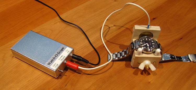
Watch-O-Scope works by "listening" to the watch being tested, measuring time between and within ticks to determine rate, beat error, and amplitude. To do this, it needs a sensitive microphone that will detect the sounds of the watch, while ignoring ambient sounds.
If there is enough demand, we will eventually produce a ready-to-use microphone stand and amplifier that you can simply plug into your computer's Line In or Microphone jack, but in the mean time, this article describes how to construct your own.
Building the microphone stand requires some basic woodworking skills. For those who do not have the desire to build one, there is an alternative, at a small convenience cost. Korg produces a clip-on microphone, the Korg CM200BK, available from Amazon or various sellers on eBay. This microphone is as effective as the one whose construction is described below, but clips onto the watch rather than holding it securely in place. This makes it a little more awkward to test in different positions or to regulate the watch while under test, but is workable.
In addition to a microphone, you will also need an amplifier to amplify the weak signal from the microphone so that it can be detected by your computer's sound card.
The microphone stand is constructed out of wood. Almost any smooth hardwood will do, such as poplar, birch, or maple. The example shown here was constructed out of birch plywood.
The following parts are needed to construct the microphone stand:
All parts except the last three can be obtained from a good hardware store, although you may need to visit a hobby shop for the brass rod or tubing.
The piezo element can be purchased on-line from a variety of sellers on eBay. These elements can also often be salvaged from musical greeting cards, where they are used as tiny speakers.
The audio cable and plug can be purchased separately from an electronic supply company, but it may be easier to just purchase a pre-made audio cable and cut one end off. A stereo cable may be used, in which case the extra wire that connects to the ring between the tip and shield of the plug is left unconnected.
The main components of the microphone stand are three blocks of wood as detailed in the plan below (click image for a high resolution PDF version):
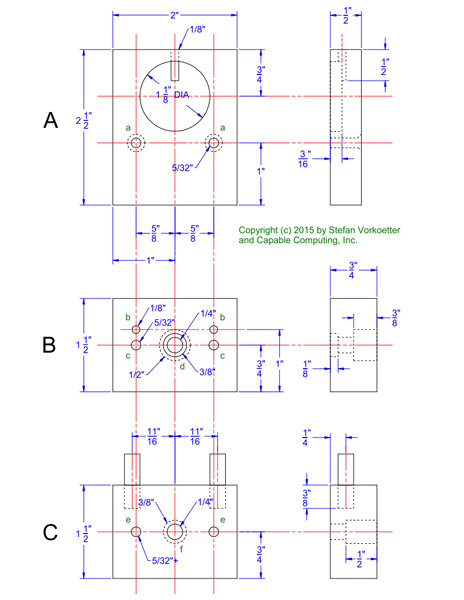
Start by cutting the three pieces to size. You will need to cut one 2" × 2-1/2" (50mm × 64mm) piece of 1/2" (12mm) thick wood, and two 2" × 1-1/2" (50mm × 38mm) pieces of 3/4" (19mm) thick wood. Grain direction doesn't really matter.
Drill 1/16" (1.5mm) pilot holes in all three blocks for the holes marked a through f. When drilling holes a and b, clamp blocks A and B together to ensure the holes line up. Likewise, when drilling holes c and e, and holes d and f clamp blocks B and C together. Also drill 1/16" (1.5mm) pilot holes, 3/8" (10mm) deep, for the dowel holes in the top of block C.
Next, drill a 1/8" (3mm) hole for the cable, 1/2" (13mm) deep, into the top of block A, centered in the width of the block, and 3/16" (5mm) back from the front face.
 Using a 1-1/8" (28mm) Forstner bit, drill the hole for the microphone element
in block A, centered 3/4" (19mm) from the top. Drill this hole 3/16" (5mm)
deep, which will expose part of the cable hole you previously drilled.
Using a 1-1/8" (28mm) Forstner bit, drill the hole for the microphone element
in block A, centered 3/4" (19mm) from the top. Drill this hole 3/16" (5mm)
deep, which will expose part of the cable hole you previously drilled.
Use a 5/32" (4mm) drill to enlarge holes a in block A to clear a #6 (3.5mm) wood screw. Using either a countersink bit, or a 5/16" (8mm) drill bit, countersink these holes on the back side of block A so the screw heads will sit flush. Also enlarge holes c in block B (but not holes b) to 5/32" (4mm).
Enlarge holes b in block B to 1/8" (3mm) so the wood screws will screw in easily, but still hold securely.
In block C, enlarge holes e to to 11/64" (4.5mm) so that the brass rods or tubes can slide through them fairly loosely.
Using a 3/8" (10mm) brad-point or Forstner bit, enlarge hole d in the front face of block B, to a depth of 1/8" (3mm). Similarly, enlarge hole f in the rear face of block C, but to a depth of 1/2" (13mm). This will give the spring space to compress into.
 With a 1/2" (13mm) brad-point or Forstner bit, enlarge hold d in the rear
face of block B, to a depth of 3/8" (10mm). This is the space that will be
occupied by the head of the brass bolt.
With a 1/2" (13mm) brad-point or Forstner bit, enlarge hold d in the rear
face of block B, to a depth of 3/8" (10mm). This is the space that will be
occupied by the head of the brass bolt.
Complete holes d and f with a 1/4" (6mm) bit. For the cleanest cuts, use a brad-point or Forstner bit again, but an ordinary twist drill will also work. If necessary, clean up the holes with a small round file. Alternatively, hole d can be drilled to only 13/64" (5mm) and then threaded with a 1/4-20 (M6 × 1) tap so that the bolt screws into the block, instead of needing to be glued in.
Drill the dowel holes in the top of block C to their full 1/4" (6mm) diameter.
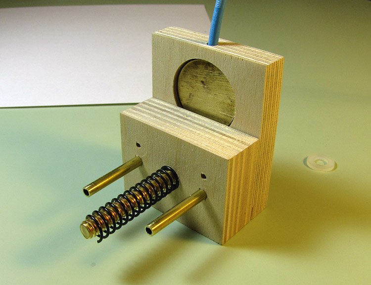
Prepare two 1-3/4" (45mm) pieces of 5/32" (4mm) brass rod or tubing. If using rod, this is most easily cut with a hacksaw, whereas tubing is best cut with a hobby-sized tubing cutter (a miniature version of the device plumbers use to cut copper pipe). File or sand the ends to a slight bevel.
Solder the audio plug to the shielded cable (or use a cable that already has a plug installed). Thread the cable through the hole in the top of block A. If the cable is a loose fit, you may want to add a layer of heat-shrinkable tubing as was done here, so that it fits the hole more exactly to prevent stress on the microphone.
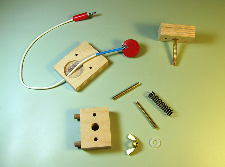
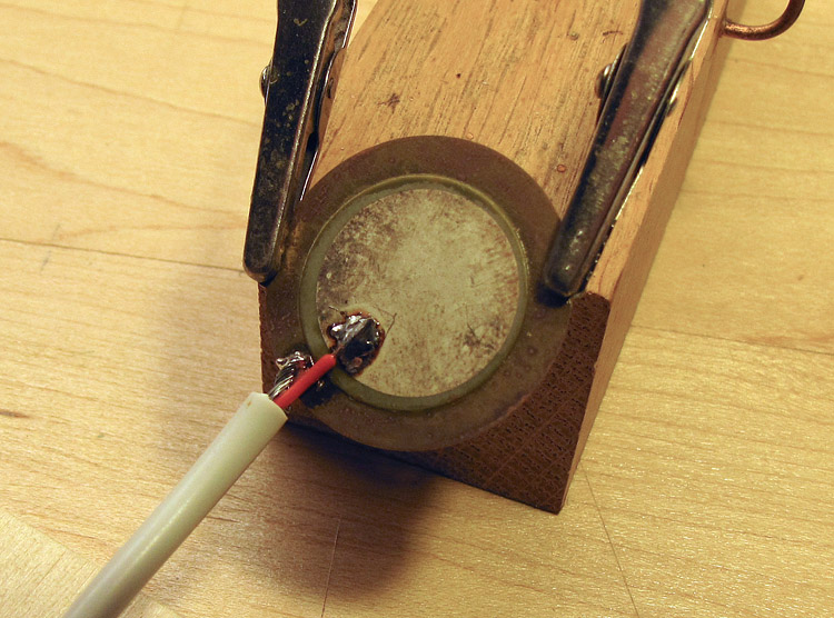
Solder the shielded cable to the microphone element after unsoldering any leads that it may have come with. The cable's outer shield is soldered to the brass disk, and the inner conductor is soldered to the microphone circle. If you are not comfortable soldering directly to the element, cut the existing leads very short (about 1/2" or 13mm) and solder those the shielded cable, being careful to avoid short circuits.
Apply double-sided foam tape to the back of the microphone, covering the entire surface except where the cable is soldered on. Before peeling off the backing, test fit the microphone to ensure it can seat firmly in its recess. If necessary, add another layer of tape, or carve away some wood to make room for the soldered connection.
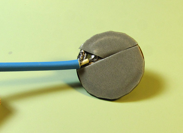
Once everything fits properly, peel off the backing, carefully slide the microphone into position, and gently press it down so the tape can take hold. Be careful that the microphone does not touch the surrounding wood, otherwise it will pick up far more ambient noise.
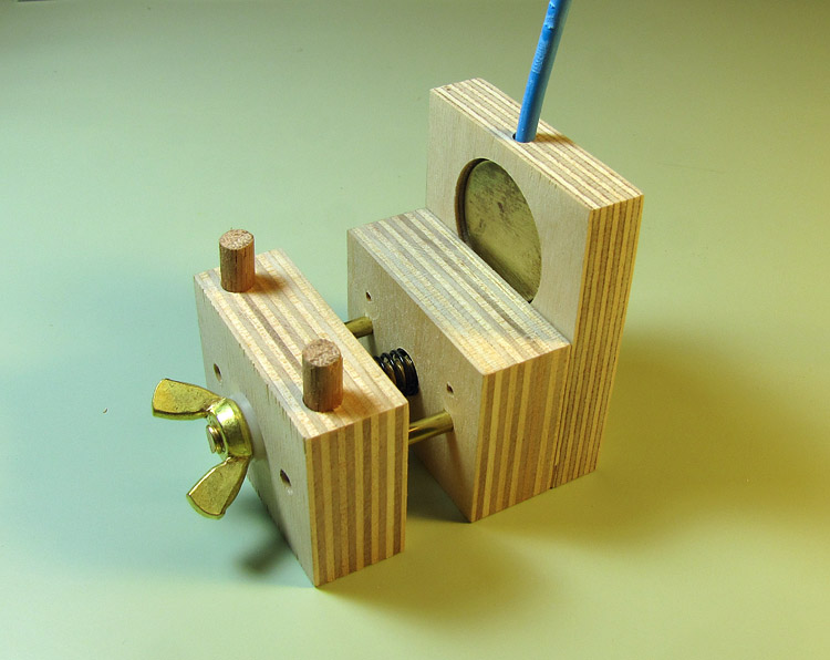
Next, insert the bolt into the back of block B, and apply a bit of glue to the bolt head so that it cannot turn. Epoxy or thick (gel) cyanoacrylate is ideal for this. Use the wing nut to hold the bolt in place until the glue cures.
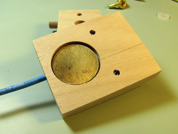
Attach block B to block A using the brass #6 × 1" (3.5 × 25mm) wood screws. If the screws are difficult to screw in, enlarge the holes slightly, as trying to force a brass screw will twist the head off. It helps to hold the two pieces together with a clamp or vice to keep them aligned while installing the screws.
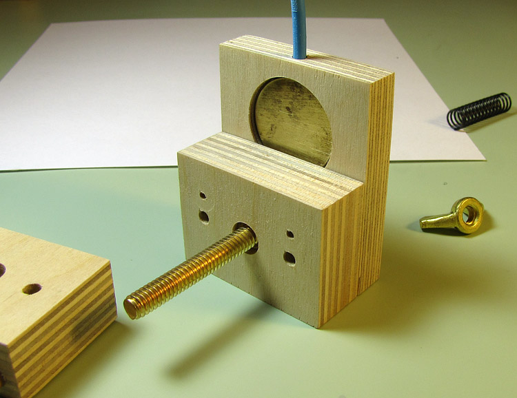
Install the two brass rods or tubes into their holes, pressing them in until they are stopped by block A. If you need to tap them in, do not hit them with a hammer directly, or you will bend them or widen the ends. Instead, hold a small block of wood over the end of the rod/tube, and tap the block gently with a small hammer.
Slide the spring over the bolt and ensure it seats all the way into the counterbored hole. Then slide block C over the bolt and rods, pressing it all the way up against block B. If it won't go all the way because the spring is fully compressed, count how many coils of the spring remain visible, and cut this many off from one end.
Once the spring is properly adjusted, install the wing nut and washer, and then press the dowels into their holes. If the fit is loose, use a bit of wood glue to secure them.
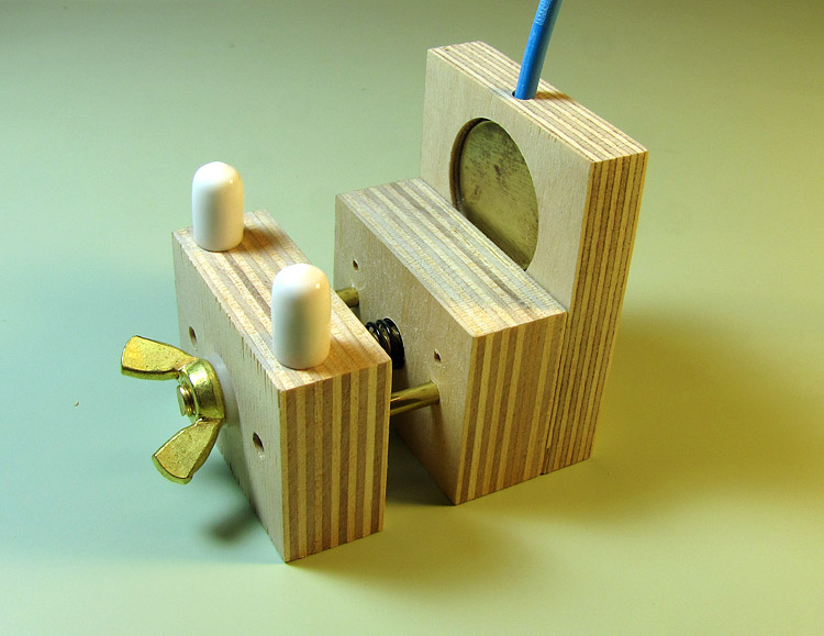
Install the vinyl or rubber caps over the dowels, trimming the dowels slightly if they are too long for the caps to cover them completely.
Clean the completed stand with a soft brush, vacuum, and a tack rag to remove any traces of sawdust. Then, to isolate the microphone from the desk or workbench it is being used on, apply soft rubber or vinyl feet to each corner of the bottom, left side, right side, and back.
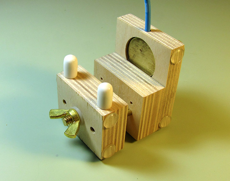
Finally, apply a thin bead of glue where the cable exits the top of the stand so that pulling on the cable does not strain the solder joints on the back of the microphone element.
Congratulations, your microphone stand is complete! Visit the amplifier page for plans and instructions on building an amplifier to interface this microphone to your PC.
Copyright © 2014-2022 by Stefan Vorkoetter and Capable Computing, Inc.
All rights reserved. Unauthorized duplication prohibited.
Watch-O-Scope is a trademark of Capable Computing, Inc.
Last updated on Tuesday November 9, 2021.