The microphone used in the microphone stand produces a very weak signal, generally on the order of 10µV, whereas a sound card is expecting a signal of about 500mV to 1V at the Line In jack, or 50-100mV at the Microphone jack. The amplifier boosts the signal level up to 6000-fold, and also helps to reject background noise.
Building the amplifier requires some electronic construction experience.
The amplifier consists of three stages, each using one operational amplifier (op-amp) of a TL074 quad low-noise op-amp IC. Each stage consists of a passive high pass filter, followed by an amplifying active low-pass filter. An additional high pass filter follows the last stage, and together, the high pass filters greatly attenuate 50Hz or 60Hz AC (mains) hum. The active low pass filters, with a cut-off frequency of about 11kHz, reduce high frequency background noise. The schematic and circuit board layout are shown below (click image for a high resolution PDF version):
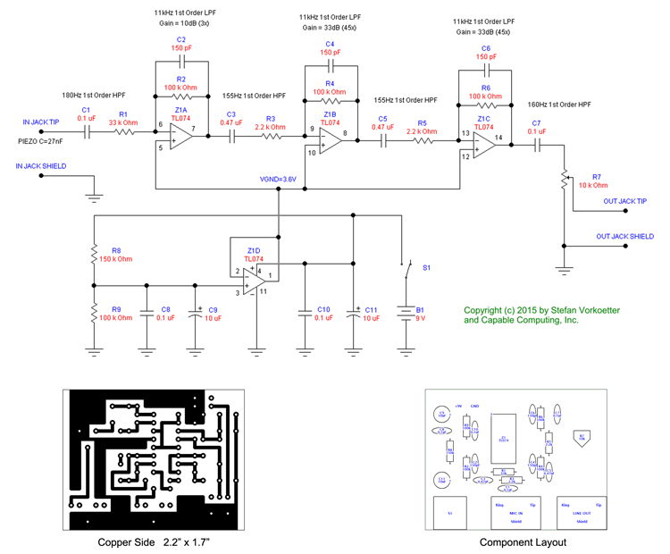
The fourth op-amp in the TL074 provides a stable "virtual ground" at about 40% of the supply voltage. This allows the entire circuit to operate from a single-polarity 9V power source (a 9V battery).
A piezo-electric transducer like the one used as a microphone in this project has a very high DC impedance and acts in a circuit like a very low-valued capacitor, on the order of 20 to 30nF. Normally, when designing a piezo amplifier for audio applications, one wants a very high input impedance in order to obtain sufficient bass response. For a watch microphone however, low frequencies should be rejected. By using a fairly low input impedance (33kΩ), the piezo transducer itself becomes part of the first high pass filter stage.
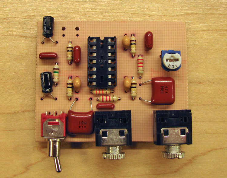
The amplifier can be constructed on a printed circuit board, or any other circuit fabrication technique you are comfortable with (an earlier prototype, for example, was constructed on stripboard). The remainder of this article assumes the use of a printed circuit board. To aid in rejection of 50Hz or 60Hz AC hum, the amplifier should be enclosed in a metal case, electrically connected to the circuit's ground. Shielded audio cable must be used for all connections to the amplifier.
The following parts are needed to construct the amplifier:
All capacitors should be rated 15V or higher. C1 through C7 should have 10% tolerance or lower. All resistors should be 1/8W or larger with 5% tolerance or lower.
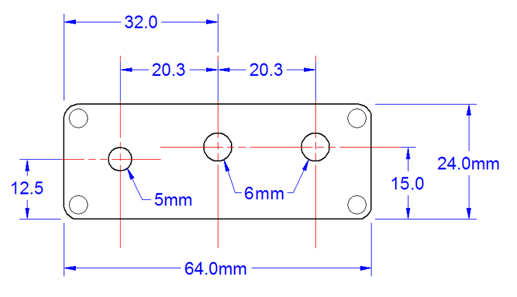
The circuit board was designed with specific jacks and a switch in mind, the technical details of which are shown here:
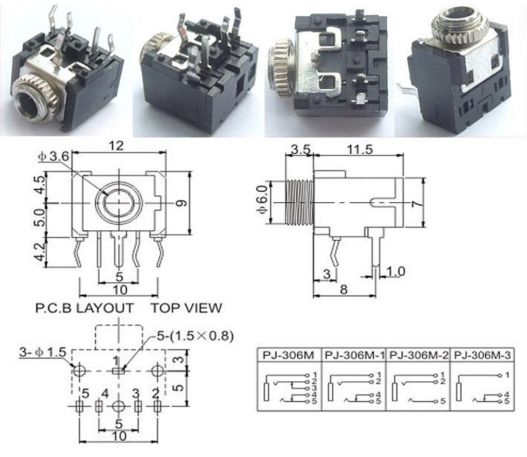
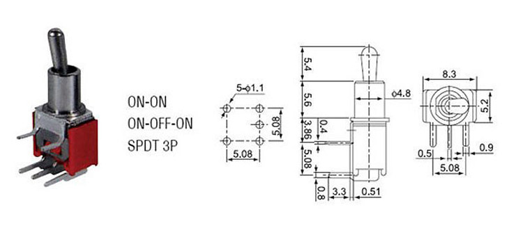
If using different parts, you may need to modify the circuit board layout to suit. Alternatively, you can use panel mount parts, connected to the circuit board by short leads.
If using a printed circuit board, prepare, etch, and drill the circuit board as shown in the plan above. One way of doing this is described in the article, Making Excellent Printed Circuit Boards. A properly scaled version of the artwork can be found in the PDF version of the plan.

Begin by installing a socket for Z1, with the notched end pointing away from the jacks and switch edge of the board. Then install all the fixed resistors, followed by the capacitors. Note that the locations for capacitors C2, C4, and C6 have three holes each. This is to allow use of two different sizes of capacitors (0.1" or 0.2" lead spacing). If using the smaller size, be sure to install the two leads into the upper pair of holes (the two holes that are not connected on the copper side of the board).
Finally install the jacks, switch, and trimmer potentiometer R7. You may need to enlarge the holes for the jacks and switch slightly.
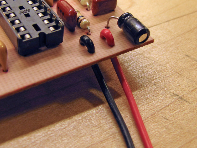
Install the battery clip next. There are two holes for each lead, with the ones closer to the edge of the board being for strain relief. Enlarge these holes to 1/16" (1.5mm) and relieve the copper around the holes with a larger drill bit. Feed the leads up from the bottom of the board, loop them over in a large loop, and then solder them into the other pair of holes. After that, pull the leads back to leave just a small loop on top of the board.
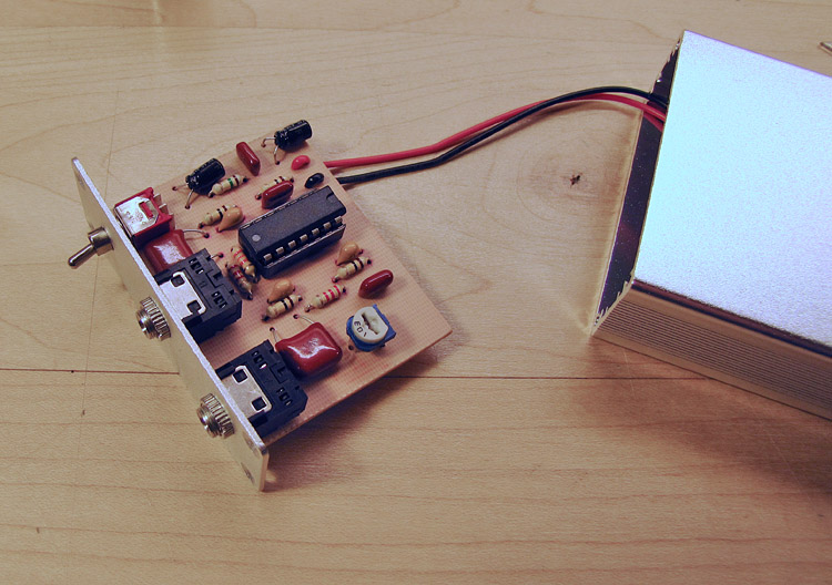
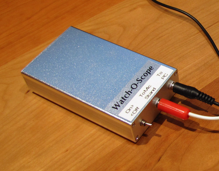
The amplifier should be enclosed in an aluminum case to shield against AC hum. A steel case should not be used, simply because it could be, or become, magnetized, which could affect the functioning of a mechanical watch. The case used here was 112mm × 64mm × 24mm, and the drawing below shows the size and location of the three holes that needed to be drilled into the panel for the switch and two jacks:
Any similar enclosure will do, so long as it has enough space to house the circuit board and a 9V battery.
Double check all your work, ensuring that the all the components are installed in the correct locations, and that the polarity of C9 and C11 is correct. Also check the board carefully for solder bridges (a magnifying glass is helpful for this). Install Z1 into its socket, with the notch at one end of the IC aligning with the corresponding notch in the socket.
Install the board into the case. If you used the jacks shown, the nuts that fasten the jacks to the case are sufficient to hold the board in place. Set potentiometer R7 to its midpoint, connect a 9V battery, and assemble the case.
Plug the audio cable into the output jack on the amplifier, and plug the other end of this cable into your computer's Line In jack. If your computer does not have a Line In jack (many laptops do not), use the Microphone jack instead.
Plug the microphone stand's cable into the amplifier's microphone jack, and place the amplifier and microphone stand in a convenient location on your workbench.
If you haven't already, download and install the Watch-O-Scope software.
 Watch-O-Scope uses your PC's sound card to receive the watch sounds
from the amplifier, so some additional configuration may be necessary. Open
the Sound and Audio applet from the Windows Control Panel, find the
audio input settings, and ensure that the Line Volume is set to
maximum. If you connected the amplifier to your computer's microphone jack,
adjust that volume instead. Depending on the version of Windows used, your
settings window might look different than the one shown here.
Watch-O-Scope uses your PC's sound card to receive the watch sounds
from the amplifier, so some additional configuration may be necessary. Open
the Sound and Audio applet from the Windows Control Panel, find the
audio input settings, and ensure that the Line Volume is set to
maximum. If you connected the amplifier to your computer's microphone jack,
adjust that volume instead. Depending on the version of Windows used, your
settings window might look different than the one shown here.
Place a running watch onto the microphone stand, dial up and with the crown touching the microphone element (the brass disk on the tall side of the stand). Lightly tighten the thumbscrew so that the crown is pressed against the piezo element. It should be just tight enough that the watch will not fall out if you turn the microphone stand upside-down. Overtightening could damage the microphone.
Turn on the amplifier and start the Watch-O-Scope program, either from the Windows Start menu or from the desktop if you elected to have the installer put an icon there.
Click the Scope Mode button (the second magenta coloured button) or press S on your keyboard, and you should see a repeating oscilloscope-like trace as shown below. The numbers at the top are not meaningful at this point, and will not likely correspond with what the watch is doing.
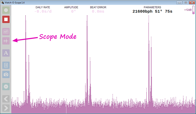
If you do not see such a trace, double check that the battery is fresh, the amplifier is turned on, the cables are plugged in correctly both at the amplifier and at the computer, and that you've set the input level for the correct input.
If you still do not see a trace, you may have to specify the audio input device that is being used in Watch-O-Scope's Settings window.
If the trace reaches all the way to the top of the window and is obviously being clipped, then the input level is too high. This can happen if using a computer's microphone input. Adjust R7 counter-clockwise to lower the level until the trace takes up no more than about half the height of the window (to leave some headroom for louder watches). If the level is too low, adjust R7 clockwise.
Before using Watch-O-Scope with your microphone and amplifier to adjust watches, you should calibrate your sound card clock so that the reported rates will be correct.
Copyright © 2014-2022 by Stefan Vorkoetter and Capable Computing, Inc.
All rights reserved. Unauthorized duplication prohibited.
Watch-O-Scope is a trademark of Capable Computing, Inc.
Last updated on Sunday May 22, 2016.